Medium Conference Room with Beamtracking Mics
This system design template shows how the Tesira Beamtracking™ microphone and the PoE amplifier can be used in a typical medium-sized conference room installation. Traditionally, these rooms are designed to allow room participants to host local meetings with one another using local presentation capabilities, as well as make conference calls to remote meeting participants over the phone (VoIP or analog POTS), a 3rd party video conference device, or using a PC-based soft codec.
In this example, the conference room will be equipped with two beamtracking pendant microphones, covering the entire seating area around the conference table. Meeting attendees will be automatically tracked and picked up by the ceiling microphones, which eliminates any user intervention. Tesira's Acoustic Echo Cancelation (AEC) technology and the TCM-1 beamtracker work together to deliver optimum speech quality to the far end participants. Ceiling speakers are located at suitable positions to evenly cover the room with the far-end voice, USB audio, or auxiliary audio. Amplification for the speakers will be provided by the AMP-450BP, a PoE powered device which may be placed in close distance to the speakers, thus reducing speaker cabling efforts and installation time. The TesiraFORTÈ AVB VT4 can also interface with analog telephone lines or a VoIP telephony system to allow for a voice-only telephone conference. There will be an HD-1 hardware dialer in the room located at the conference table as an additional control point for dialing functions.
Room design
![]() Room Functionality Scope:
Room Functionality Scope:
- Two ceiling pendant microphones with beamtracking technology
- Integration of 3rd-party video conference codec
- Connection to building phone system (VoIP and/or analog POTS)
- USB connection to local PC for soft codec
- Stereo program source audio inputs
- System control via third-party control system, and HD-1 dialer hardware.
- LoZ ceiling speakers for playback of voice signals (VTC, VoIP, soft codec)
Equipment list
Below is the list of Biamp equipment used in this project:
- 1 - TesiraFORTÉ AVB VT4 4 mic/line level inputs with AEC; 4 mic/line level outputs with integrated VoIP, POTS, and USB audio
- 1 - Tesira TCM-1 AVB beamtracking ceiling microphone
- 1 - Tesira TCM-1 EX Extension beamtracking ceiling microphone
- 1 - Tesira AMP-450BP 4-CH PoE+ backpack amplifier providing 4x 50 Watts burst power with RJ45 speaker outputs designed for use with Desono C-IC6 speakers
- 1 - Tesira HD-1 Dialer Hardware-based dialer; 12 button dial pad with access to all Tesira telephony functions, PoE-powered
- 4 - Desono C-IC6 Wide coverage two-way, passive coaxial design ceiling speakers (dispersion angle of 130°) optimized for voice reproduction
- 1 - TesiraCONNECT TC-5 5 port AVB room expander with 120W of PoE+ budget.
Note that other non-Biamp equipment is required, such as Soft Codec, Video Conference Codec, and Aux Sources.
System configuration
The example file for this system design template is set up with all the audio I/O, processing, and control points required, and is ready to load to the system and begin setting up the room gain structure and EQing. In the file, the matrix routing is already in place to support the room design requirements. Two AEC processing channels on the TesiraFORTÉ AVB VT4 will be occupied by the TCM-1 microphones. The first two analog audio inputs will be receiving the line input signal from the external video conference codec. The second two analog audio inputs are used for stereo audio feeds from auxiliary sources. One analog output will be required to send the local signal to the VTC line input, the far end.
The room speakers will be connected directly to the networked AMP-450BP and do not occupy any further analog outputs on the DSP. Every output channel is represented individually on the mixing matrix, to accommodate for different room/speaker setup scenarios. An example of valid scenarios would be:
- Creating four individual ceiling speaker zones, might incorporate Stereo L/R routing, if applicable.
- Front Stereo L/R speakers with up to two zones of ceiling speaker rear fills.
To assist with deployment and commissioning of systems which include the desono C-IC6, a Tesira Library File (.tlf) has been created. This includes a custom block with Biamp's recommended EQ curves to optimize the sound of the C-IC6 loudspeaker. This custom block has been included in this system design template file. These blocks can also be found in the Processing Library in Tesira software.
To support the conferencing needs of the space, the microphone signal is routed to the VTC, VoIP, analog telephone (POTS) and USB outputs. USB initialization in the file has been setup to support a 1ch x 1ch audio configuration with computer AEC disabled for the PC connection. All AEC references have been made in the matrix mixer for proper echo cancelation of conferencing sources. All conferencing devices are cross-mixed among each other to allow the use of multiple distance-conferencing methods at the same time.
The file's Equipment Table is populated with proper hardware to match the layout, but will need to have serial numbers and proxy host assignments added before loading the file to system.
Even though the analog telephone interface is considered an optional method for conferencing in this design template, it can be found pre-configured in the system configuration file. Either VoIP or POTS may be used on demand to accommodate for the preferred connection method with the telephone system.
Tesira software and firmware version 3.14 includes a new Parlé Processing block that is a pre-configured signal processing block necessary to properly utilize the Parlé Beamtracking series of microphones. The attached design template file utilizes this processing block in the configuration with AEC processing selected to reside outside the Parlé Processing Block.
The .zip file below contains the example Tesira configuration files for this conference room application.
Medium Conference Room with Beam Tracking Mics.zip
![]()
Networking details
This conference room application will make use of PoE and PoE+ powered endpoints, which connect to the TesiraFORTÉ server-class device and exchange AVB audio and control data. In regards to cable types and lengths, the common rules to gigabit Ethernet cabling do apply. While the TCM-1 host microphone, as well as the AMP-450BP will communicate via AVB only, the control port of TesiraFORTÉ must be able to communicate with the HD-1 dialer. The simplest way to realize a functioning system, is using a converged network on one TesiraCONNECT as shown in the drawing above. Static IP addresses may be assigned to the HD-1 or TesiraFORTÉ if desired, but make sure to change the remote device first and the Proxy device (in this case TesiraFORTÉ) last. For a more detailed guide on how to implement in a larger range of network applications, it would be helpful to reference our Tesira Network Infrastructure article.
Setup Requirements:
- The TesiraCONNECT TC-5 device provides 5 ports of AVB and 120W of PoE+ budget. This provides full PoE+ power on 4 ports.
- The TesiraFORTE is configured with single network connection topology. Optionally, separated networks may be configured by connecting the control port to a separate control network switch.
- A standard network cable (Cat.5 or higher) to connect the TCM-1 with the TCM-1EX.
- Do not exceed 33ft or 10m on this link
- This is a proprietary digital audio link, not compatible with Ethernet
- The HD-1 is configured to receive an IP address by a DHCP server on the network or via Zeroconf addressing scheme.
- Note that the TCM-1 and the AMP-450BP use Layer 2 AVB for audio and control data, IP address setup is not required.
After these control and AVB network setup steps are complete, you will now be ready to send your compiled system configuration to the hardware.
Microphone and speaker placement
The room
Arguably the single most important element in a conference system is the room itself. A noisy and reverberant room will generally sound awful for conferencing. A properly designed room with controlled reverberation and low noise floor will generally sound good for conferencing.
The importance of creating a controlled acoustic environment cannot be overstated. It is important to make the room as quiet as possible (lower noise floor) and minimize reverberance (shorter RT60) in preparation for installing the conferencing system. When properly applied, soundproofing and acoustic treatments will yield dramatic improvements in performance for most rooms.
Microphone placement
Even though the TCM-1 beamtracking microphones use state of the art technology to track a person's voice, 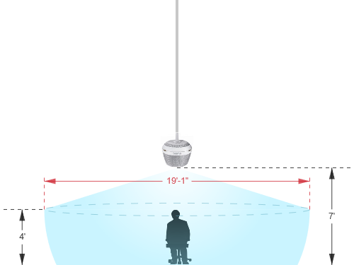 while reducing unwanted background noise, the laws of physics can't be ignored when deciding on the right placement of a microphone. A good signal-to-noise ratio is key in every part of the audio signal chain and for a typical microphone pickup scenario, this translates to avoiding large distances between the mic and the talker. The Parlé ceiling microphone calculator will help to find the right pendant height and required distance between the two pendants for the the expected coverage area. Here are a few more tips to an ideal microphone placement:
- Keep the distance to the talker as short as possible.
- Keep the distance to the ceiling speakers as high as possible.
- Stay away from noise sources like projector fans and air vents.
Speaker placement
Placing speakers in a room can be as equally critical as finding the right spot for a microphone. Biamp has provided a Ceiling Speaker Calculator that can be used to determine the coverage required for the desired application. An ideal positioning of multiple ceiling speakers will achieve an even SPL coverage and a good speech intelligibility across the entire room. In order to get a better sense on how much SPL the speaker of choice is able to produce with the given power of our AMP-450BP amplifier, the Amplifier Power Calculator will provide some answers. In addition to that, a speaker simulation software might be able to predict the expected in-room STI values.
In this example, the speakers are not being used for voice-lift or similar live speech reinforcement, hence gain before feedback doesn't have to be considered. Still, avoiding short distances between the speakers (far-end audio) and the microphone will help to improve the AEC performance.
Audio setup
- The line level inputs to receive the VTC far-end signal are designed as two-channel, or left and right inputs, as it reflects the connection scheme of some Vodeo conference codecs in the market. However the actual signal might be mono. More info on interconnecting and properly setting up a 3rd party VTC with Tesira can be found here: VTC with Cisco TelePresence Codecs. In this scenario, it is recommended to disable AEC inside the VTC.
- Follow Gain Structure best practices to set input and output levels of microphones and sources. Input and output gain levels have been left at default settings for integration flexibility of the file. Input and Output metering has been added to assist with setting gain structure within the file. Additional meters can be added to the file as required to allow for additional detail at point along the signal path.
- Ensure that the proper VoIP and/or Analog Telco setup is done and the system is ready to make and receive calls.
- Connect USB to PC for soft codec integration if required. Reference the USB interface setup document if needed.
- Reference AEC best practices documentation and begin to do some test calls with the system. ERL values between 0dB and +15dB are optimal.
- Level and mute controls have been added to the file pre and post matrix mixer. These are added for flexibility to meet the design criteria and tastes of the client or integrator. These level controls have been left with their default maximum and minimum values in place, but can be adjusted to fit the needs of the space.
- The HD-1 hardware has tactile controls for level and mute functions. It is important to note that these control level and mute parameters on the VoIP or telco blocks themselves, and cannot be assigned to the standard level controls.
- Uber Filters have been added to all signal paths to allow for any additional equalization as needed to sources. It is recommended to use the advanced filters section of the AEC channel processing block for for any high pass filtering needed on conference table microphone inputs. Additional filtering or dynamics blocks may be added or changed as needed to achieve the desired results in the file.
- Changes to matrix mixer can be made as needed to allow for appropriate sources to feed the speakers to fit the design application.
VoIP setup
If a VoIP phone line is to be used, it must be correctly configured to register with the in-house VoIP phone system. Biamp VoIP interfaces have been tested and/or certified to work with the VoIP telephony systems listed here. Biamp VoIP interfaces may also be able to work with other SIP-based VoIP systems, but they haven't been tested or certified with those systems.
When integrating Tesira with one of the tested/certified VoIP systems, it is best to follow the detailed instructions in the appropriate article to ensure a successful deployment. Detailed instructions can be found in the following articles:
- Microsoft Lync / Skype For Business
- Cisco CallManager
- ShoreTel
- Mitel 3300 ICP configuration for a Tesira SVC-2 or TesiraFORTÉ VI
- Avaya Session Manager
- Avaya SES
- Avaya IP Office
- Avaya Communication Server
The basic steps to configure the VoIP interface start with opening the VoIP Control/Status block configuration dialog to access VoIP settings:
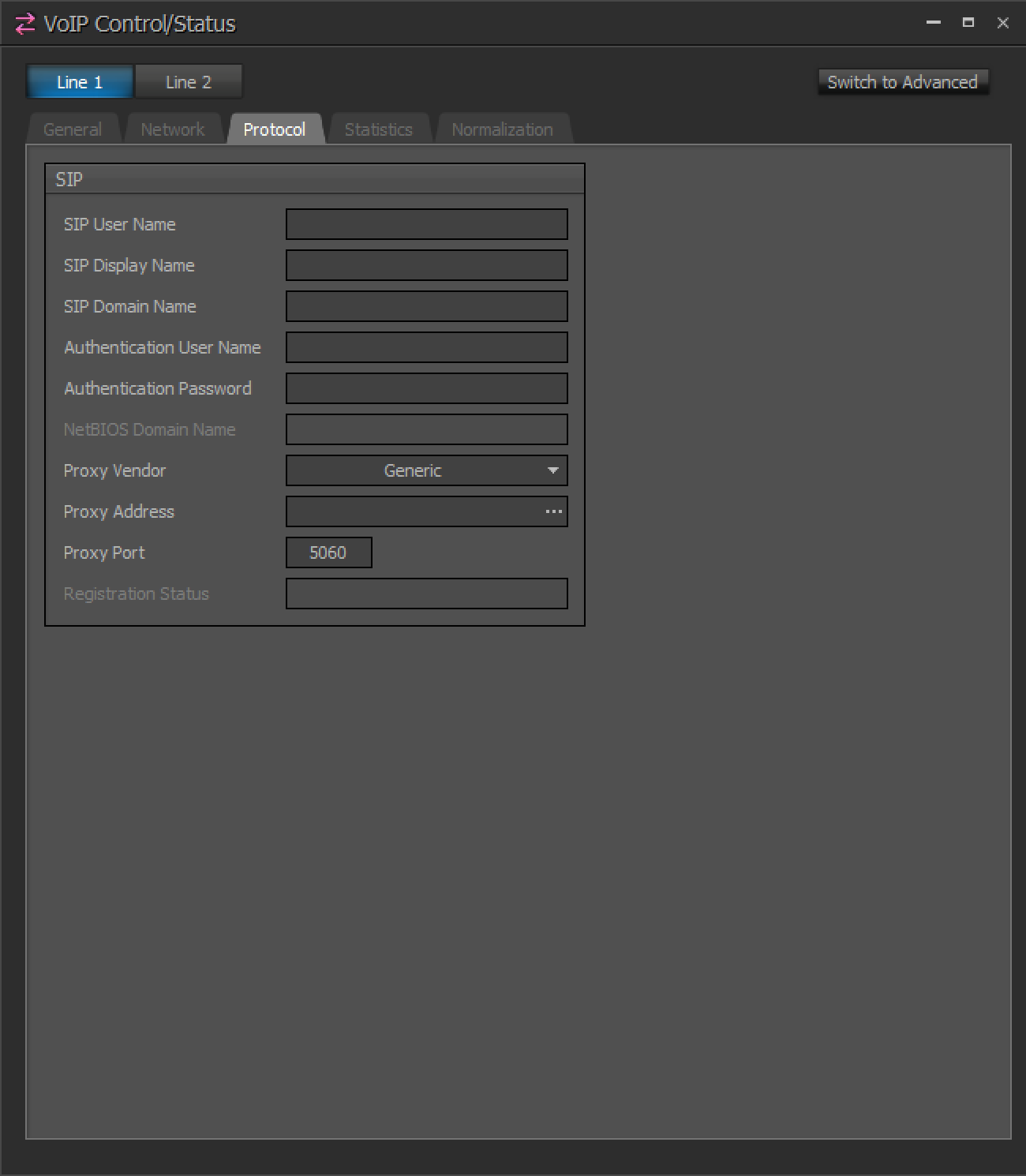
(Click to see configuration dialog)
There are some required fields in the Network and Protocol tabs of the VoIP Control/Status block that must be filled in correctly for successful VoIP endpoint registration:
Network Tab:
- IP Address / Netmask /Gateway - The VoIP card must have an appropriate IP configuration for the network it is connected to
- VLAN Tagging - If the VoIP card is on a "tagged" VLAN, this must be enabled and the correct VLAN ID must be provided. If the VoIP card is on an "untagged" VLAN (or no VLAN), this should not be enabled.
Protocol Tab:
- SIP User Name - This is usually the extension number that the VoIP interface will use.
- Authentication User Name / Password - The username and password required to authenticate this extension.
- Proxy Vendor - Selecting the correct vendor will ensure that the VoIP interface correctly tailors its communications to the VoIP system.
- Proxy Address - The IP address of the VoIP proxy server (also known as: VoIP server, Call Manager server).
Much of the above information must be obtained from the customer's IT or VoIP team. The following document was designed to facilitate the process of obtaining this information. Provide this documentation to the IT/VoIP team and ask them to fill it out:
VoIP Checklist Form
Control integration
HD-1 Setup: The HD-1 dialer in this system is a standard Ethernet device and requires 802.3af Class 1 PoE. The default network configuration of HD-1 units is DHCP, so if there is no DHCP server on the Tesira network the units will revert to link local addressing (169.254.xxx.xxx, netmask 255.255.0.0) schemes. The HD-1 will display "Waiting for Configuration..." on the screen until a configuration file has been loaded to the Server associating it by its Device ID. The Device ID of the HD-1 is used to associate the block with the physical HD-1, it needs to be set in 2 places: the HD-1 processing block and in the HD-1 hardware. The HD-1 must be associated with a specific telco card in the software. The HD-1 and telco card will then share an identification number seen at the bottom right corner of the blocks. It is also important to note that the buttons on the HD-1 have fixed functionality and cannot be programmed in the software to perform specific functions. The complete HD-1 configuration article can be found here.
Control System Integration: The example Tesira configuration file for this application file has been setup to allow third-party control systems to easily control the Tesira system. There are control points for Dialing, Level, Mute, and Mic Logic already in place to allow for you to use as it as-is, or add to as needed to suit the needs of the client. Control points within the file have been noted with an additional text box showing their default instance ID tag. These tags can be changed as needed to suit the programmer workflow or standardization.Design Template - Medium Conference Room with Beamtracking Microphone
Further reading
- Parlé-series Beamtracking Microphones
- Parlé ceiling microphone calculator
- Parlé-series microphones tips and tricks
- Parlé Processing block
- Ceiling Speaker Calculator
- Amplifier Power Calculator
- Calibrating AEC in Tesira
- Burst Mode in Biamp PoE+ amplifiers
- Specifying PoE switches for Biamp Tesira devices
- TesiraCONNECT
- Integrating desono loudspeakers and AMP-450BP backpack amplifiers