Distance Learning Classroom
This system design template describes how Tesira products can be used in a large classroom setting with 100 students. Lectures have traditionally been the pedagogical method used for large classrooms and lecture halls. However, as the classroom has evolved, along with student expectations, we have seen the important role that technology can play in engaging and empowering student participation.
In this example, the system is designed to provide every two students with a push-to-talk microphone, utilizing mix-minus speaker zones for local reinforcement. This will ensure that every voice can be heard and facilitate student interaction. Video distribution, driven by Tesira Lux, will support laptop presentations from both teacher and students, as well as PTZ camera feeds for lecture capture and video conferencing. The video conferencing system, in conjunction with VoIP integration, supports distance learning and remote presentation capabilities. The Tesira system is designed with control points to integrate with third-party control systems for various level, mute, dialing, and routing functions.
Room design
Room Functionality Scope:
- 50 push-to-talk gooseneck microphones (one for every two students)
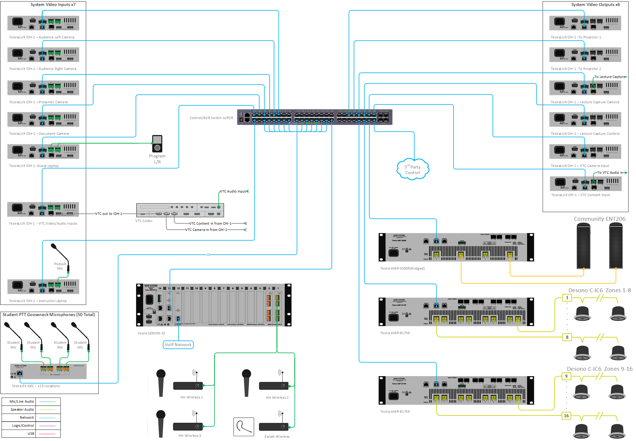
- Podium microphone at teaching station
- 4 wireless microphones, (1) earset and (3) handheld
- Ceiling loudspeaker system zoned for mix-minus, providing reinforcement of all microphones
- Stereo program audio speaker system
- Two ceiling-mounted projectors
- Audio Conferencing with VoIP
- Video Conferencing with 3rd party codec
- Lecture Capture System
- 3 PTZ cameras (to capture Audience Left, Audience Right, and Teaching Station)
- Document camera
- Auxiliary program audio source
- Laptop inputs for both instructor and student connections
- Video distribution with TesiraLUX
- System control via 3rd party control system

Equipment list
Below is the list of Biamp equipment used in this project:
- 1 - Server-IO AVB SEC-4 (2), SVC-2 (1), DSP-2 (2)
- 13 - EX-AEC 4-channel mic/line level input expander with AEC (acoustic echo cancellation)
- 13 - UTMK-1 Under table mount for expander device
- 2 - AMP-8175 Eight channels; 175W per channel, Dual AVB ports (16 direct drive mix minus zones)
- 1 - AMP-4350R Four channels; 350W per channel, Dual AVB ports (Program L/R Audio)
- 7 - TesiraLUX IDH-1 Video encoder connected 1G
- 6 - TesiraLUX OH-1 Video decoder connected 1G
- 32 - Desono C-IC6 Wide coverage two-way, passive coaxial design ceiling speakers (dispersion angle of 130°) optimized for voice reproduction
- 2 - Commmunity ENT206 Two-way Compact Column Point Source Loudspeaker; 6 LF Drivers, 2 High Frequency CRE arrays, 2-way crossover, 150 continuous @ 8 ohms
Note that other non-Biamp equipment is required, including, but not limited to, AVB enabled network switch, push-to-talk microphones, document camera, projectors, PTZ cameras, video conferencing codec and lecture capture appliance.
Example file
 The example file for this system design template is set up with all the audio I/O, processing, and control points required, and following device assignment within the equipment table, will be ready to load to the system and begin setting up the room gain structure.
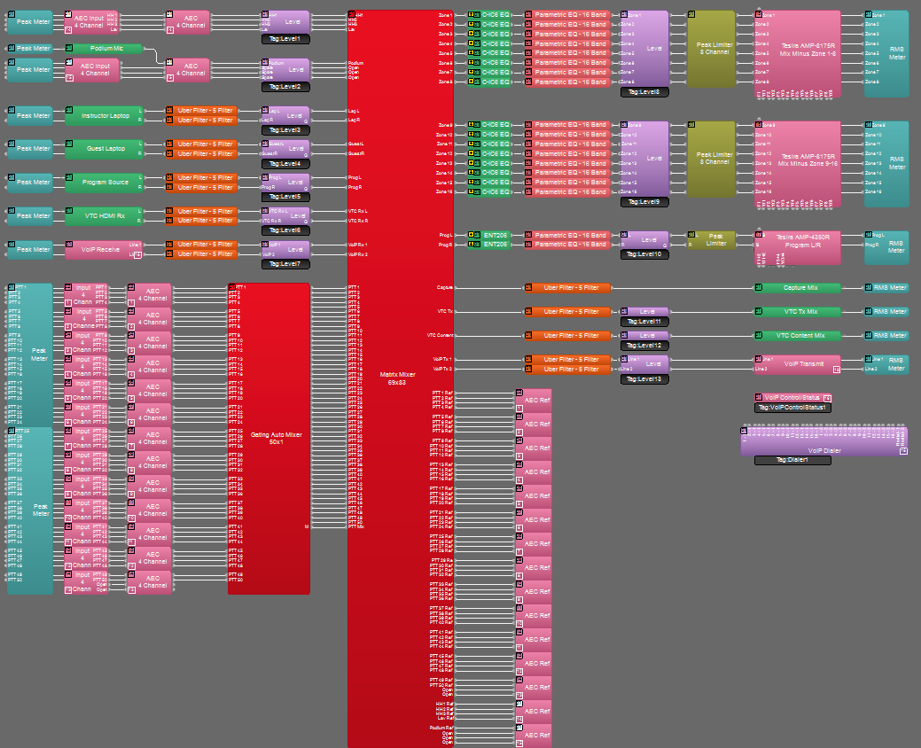
The 50 student push-to-talk microphones will utilize EX-AECs, which could be mounted underneath student workstations using Under Table Mounting Kits (UTMK-1). These microphones are routed through a single gating automixer, configured with direct outputs enabled to facilitate the mix-minus routing. Mix-minus routing has been set within the system's main matrix mixer; however, this is a starting point and additional attenuation and routing adjustments may be required depending on the environment. The 4 wireless microphones are connected directly to the SEC-4 card in Slot 1 of the Tesira Server IO. The podium microphone connects to an audio input on the Podium Laptop IDH-1 and uses the AEC processing associated with Server IO Slot 2 Channel 1.
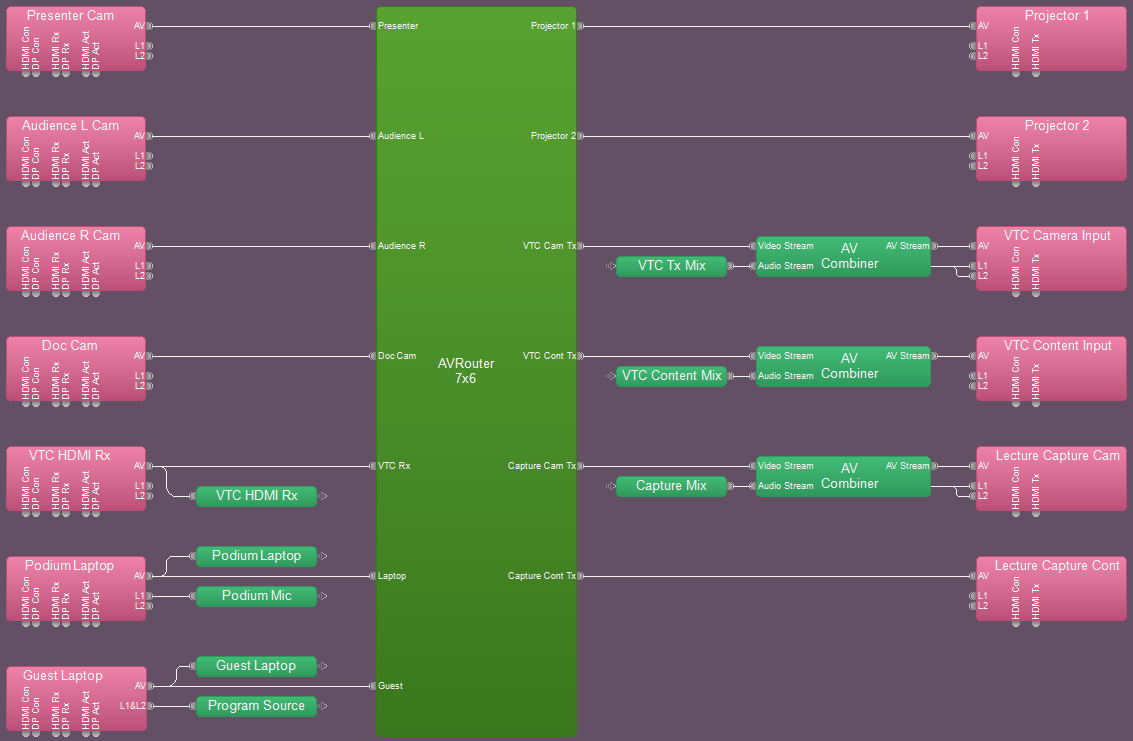
The video partition has all input and outputs connected to a single AV Router. Partition connectors are used to de-embed the HDMI audio to the audio partition. Audio mixes are returned to the video partition and re-embedded using the AV Combiner blocks.
A sample of presets have been provided to support video and associated audio routing, as well as privacy mute. Additional presets can be added, as needed.
To assist with deployment and commissioning of systems which include the Desono C-IC6 and Community ENT206 speakers, a Tesira Library File (.tlf) has been created. This includes custom blocks with Biamp's recommended EQ curves to optimize the sound of the included loudspeakers in this design. The custom blocks have been included in this system design template file. These blocks can also be found in the Processing Library in Tesira software.
The .zip file below contains the example Tesira configuration files for this application.
File Download: Distance Learning Classroom.zip
Networking details
The Distance Learning Classroom system requires both control and AVB networks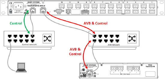 , utilizing an AVB capable network switch.
Setup Requirements:
- 30 AVB+Control enabled ports with 13 having PoE+ (minimum PoE+ budget of 300W)
- Additional ports as required to support VoIP, VTC, and 3rd party control
- Configure VLAN for control traffic (AVB automatically creates its own VLAN)
- This may not be required if using physically separated networks as shown in the diagram on the right
- Enable separated networks for SERVER-IO AVB
- Enable SSH/Telnet in Server IO for 3rd Party Control
Audio setup
- Follow Gain Structure best practices to set input and output levels of microphones and sources. Input and output gain levels have been left at default settings for integration flexibility of the file. Input and Output metering has been added to assist with setting gain structure within the file. Additional meters can be added to the file as required to allow for additional detail at point along the signal path.
- Make attenuation adjustments to speaker zone cross points within the matrix mixer, as needed, to adjust mix-minus zones
- Make sure VoIP is set up and the system is ready to make and receive calls. Additional information pertaining this can be found in the VoIP setup section below.
- Connect the room VTC system to the appropriate input and outputs on the Server IO. Adjust Full Scale (dBu) output level to match sensitivity of VTC input. Be sure to reference audio settings in VTC system to disable AEC, and change mic/line settings as needed. Reference the VTC setup documents to assist with any troubleshooting.
- Connect the appropriate output of the Server IO to the lecture capture device. Adjust Full Scale (dBu) output level to match input sensitivity and make input setting adjustments to lecture capture device as directed by manufacturer user documentation.
- Reference the AEC best practices documentation and perform test calls with the VoIP and VTC systems: ERL values between 0dB and +15dB are optimal. Note that Noise Min (located in the Advanced Filters section of the AEC processing block) has been set to -55dBu to account for the push-to-talk and wireless microphones.
- Level and mute controls have been added to the file pre and post matrix mixer. These are added for flexibility to meet the design criteria and tastes of the client or integrator. These level controls have been left with their default maximum and minimum values in place, but can be adjusted to fit the needs of the space.
- Uber Filters and Parametric Equalizers have been added to allow for any additional equalization as needed. It is recommended to use the advanced filters section of the AEC channel processing block for for any high pass filtering needed on the microphones. Additional filtering or dynamics blocks may be added or changed as needed to achieve the desired results in the file.
VoIP setup
If a VoIP phone line is used, it must be configured to register with the in-house VoIP phone system. Biamp VoIP interfaces have been tested and/or certified to work with the VoIP telephony systems listed here. Biamp VoIP interfaces may also work with other SIP-based VoIP systems, but haven't been tested or certified with those systems.
When integrating Tesira with one of the tested/certified VoIP systems, it is best to follow the detailed instructions in the appropriate article to ensure a successful deployment.
Detailed instructions can be found in the following articles:
- Microsoft Lync / Skype For Business
- Cisco CallManager
- ShoreTel
- Mitel 3300 ICP configuration for a Tesira SVC-2 or TesiraFORTÉ VI
- Avaya Session Manager
- Avaya SES
- Avaya IP Office
- Avaya Communication Server
To configure the VoIP interface open the VoIP Control/Status block configuration dialog to access VoIP settings:
![]()
Click to see configuration dialog.
For VoIP endpoint registration, fill in the required fields in the Network and Protocol tabs of the VoIP Control/Status block:
- Network Tab:
- IP Address / Netmask /Gateway - the VoIP card must have an appropriate IP configuration for the network it is connected to.
- VLAN Tagging - if the VoIP card is on a "tagged" VLAN, this must be enabled and the correct VLAN ID provided. If the VoIP card is on an "untagged" VLAN (or no VLAN), this should not be enabled.
- Protocol Tab:
- SIP User Name - this is usually the extension number that the VoIP interface will use.
- Authentication User Name / Password - the username and password required to authenticate this extension.
- Proxy Vendor - selecting the correct vendor will ensure the VoIP interface correctly tailors its communications to the VoIP system.
- Proxy Address - the IP address of the VoIP proxy server (also known as: VoIP server or Call Manager server).
Much of the above information must be obtained from the customer's IT or VoIP team. The following document was designed to facilitate the process of obtaining this information. Provide this documentation to the IT/VoIP team and ask them to fill it out:
VoIP Checklist Form
Video setup
- The AVB network in this Large Distance Learning Classroom supports 1G connections, so
 the default 1080P-1G Bandwidth Profile with light compression will be used.
 - Make all HDMI and DisplayPort connections to encoder and decoders as needed
- Utilize built in encoder and decoder test patterns to verify video routes and HDMI outputs.
- The laptop and guest inputs should have their input EDID constrained to 1080p modes due to the unknown user devices that will be attached. Constraining the available supported input modes will mitigate aspect ratio, frame rate and resolution issues that will appear with a wide array of user devices.
- The output operation mode on the decoders is typically fine at the default of EDID Preferred, but may need modified for lecture capture or VTC devices.
- Various HDMI sources need verified with audio meters. Digital audio sources are generally referenced to full scale and require attenuation to match the gain structure of mic-level and line-level sources. Automatic gain blocks can also combat various user devices and content types with different volume levels.
- Dynamic Delay EQ in TesiraLUX will automatically operate to retain synchronization with all video end-points regardless of how audio is processed in the DSP. The output blocks of the DSP may also be added to the same delay EQ group as the video blocks. This will automatically synchronize all video and audio AEC processing pathways.
- Video routing control can be handled using presets, TTP control of an AV Router block, or via logic. Also consider that the matrix mixer on the audio partition may require adjustments.
- Serial command string blocks or GPIO triggers can be used to control the power states of projectors, displays, lighting and other devices.
- Logic can be used to create automatic input switching and source routing.
 the default
 Control integration
Control System Integration: The example Tesira configuration file for this system design template has been setup to allow third-party control systems to easily control the Tesira system. Suggested control points for Dialing, Level, and Mute already in place to allow for you to use as-is, or add to as needed to suit the needs of the client. Control points within the file have been noted with an additional text box showing their instance ID tag. These tags can be changed as needed to suit the programmer workflow or standardization.
Presets are a helpful tool, especially when having to make simultaneous audio and video routes. Presets can be recalled by Preset ID, Preset Name, or using external logic controls in conjunction with Preset Button blocks. Some initial presets have been provided to highlight routing that may be required in a system such as this. Note, that a preset may contain blocks from both audio and video partitions.
For Control Systems: Tesira systems can be accessed via Serial, telnet, or SSH depending on the networking requirements and needs of the site these settings will have to be enabled before the Tesira will be able to respond to commands. All are enabled in Device maintenance, Serial ports are enabled in the Port settings dialog, while telnet and SSH are enabled under network settings. Biamp has a calculator provided on this site to allow a programmer to generate needed commands. The command string calculator can be accessed from the main Support page and can reduce the amount of time needed to generate the commands.
Further reading
- Tesira Network Infrastructure
- Gain Structure
- Loudspeaker Equalization
- VoIP
- AEC
- Calibrating AEC in Tesira
- Separated or converged Control and AVB networks
- Auxiliary analog audio I/O in TesiraLUX
- Video bandwidth controls in TesiraLUX
- Video network design
- Desono C-IC6 conferencing loudspeaker
- Community ENT206 column speaker